FURUKAWA ROCK DRILL CO.,LTD

Furukawa Company Group

Drifter

The most important equipment of FRD products is Drifter.
You may know the spirits of FRD for knowing our drifter productivity and technology.

1. Introduction

Furukawa Rock Drill (FRD) is a general rock drill manufacturer. This paper looks back at the history of rock drills, the product that we make, examines the technological changes that have occurred to create the rock drills we see today, and looks at the current technological trends in this field.

1.1. What Are Rock Drills?

Before discussing the way rock drills have changed over time, let us first define what exactly a rock drill is.
As you would imagine, a rock drill is a machine used to drill rock; that is, to make a hole in rock, and is mainly used to drill holes for charging gunpowder when blasting bedrock.
Rock drills are broadly classified into three types based on the drilling principle: top hammer drills, down-the-hole (DTH) drills, and rotary drills.
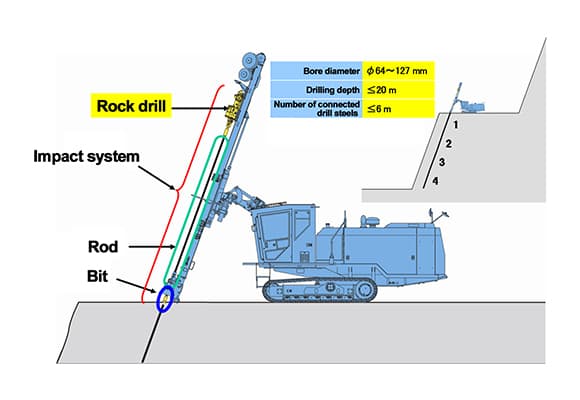
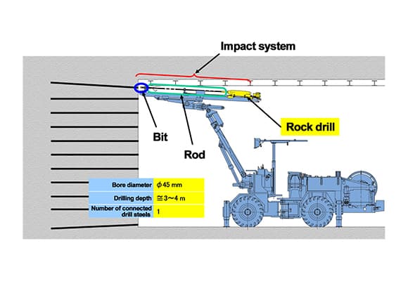
A top hammer drill has a long rod known as a drill string to which a bit is attached to the end. In the same way as a chisel is hit by a hammer, the top of the drill string is hit by a hammer known as a drifter, which crushes the rock.
A DTH drill has a drill string with a drifter attached to the end, which is located in the bottom of the hole. Rock is crushed by directly striking the bit attached to the drifter.
A rotary drill crushes rock by applying crushing force to the bit on the end of the drill string, which is pressing into the bedrock.
Although the placement of the drifter differs, with both top hammer drills and DTH drills, what contributes directly to bedrock crushing is exclusively impact. The percussive energy that is generated by the impact is transmitted to the bit in the form of stress waves (particle speed variations). The particle speed variations that occur very quickly at the bit tip allow the bit to penetrate the rock, crushing the bedrock. At that time, in order for the percussive energy to be reliably transmitted to the bedrock, the bit must stay in contact with the rock. For the bit to stay in contact with the rock, down pressure (thrust) must be applied to the drill string.
Rotary drills, on the other hand, make the bit penetrate the bedrock by quasi-statically pushing the bit into the bedrock. It is therefore the down pressure (thrust) on the bit that contributes significantly to crushing the bedrock. If you compare the features of top hammer drills and DTH drills, drills for which impact directly contributes to crushing the bedrock, you can see that with top hammer drills, the drifter is placed at the top of the drill steel; that is, outside the hole. This means that there are few size constraints, and the shape of the piston (hammer) that is in contact with the target bedrock can be optimized to have approximately the same diameter as the drill string, which is ideal from an energy transmission efficiency viewpoint. It is also easy to use hydraulic and other high-power driving sources for the piston.
One downside, however, is that the deeper the hole, the more the impact energy attenuates as it is being transmitted along the drill string, which tends to lower the performance.
DTH drills, on the other hand, have the drifter located at the bottom of the hole. This means that there are significant size constraints, and compared to a top hammer drill, the piston diameter must be relatively smaller than the bore hole diameter. Moreover, because it would be difficult to remove a driving medium that was fed to a drifter located at the bottom of the hole, a pneumatic driving source that does not need to be removed is usually used for DTH drills, making them inferior to top hammer drills in terms of power.
On the other hand, as the drifter is located at the bottom and directly impacts the bit, the output remains stable regardless of the depth of the hole, giving DTH drills the advantage over top hammer drills in deep hole drilling. With DTH drills also, because the drifter is located at the bottom of the hole, the bore hole diameter, and by extension the drill string diameter, can be wide, allowing for a more rigid drill string and straighter holes, which is also advantageous when drilling deep holes.

1.2. The Rock Drills Discussed

Only the top hammer drill will be discussed in this paper. Moreover, the discussion will be limited to the drifter of the top hammer drills, which will henceforth be called the "rock drill."
There are two main types of top hammer drills: crawler drills that are used for opencast mining; and drill jumbos that are used for operations such as tunnel boring. Both types are mainly used to drill holes for charging gunpowder when blasting bedrock.

The basic functions and structure of crawler drills and drill jumbos. These drills consist of a rock drill that slides along the top of a slide mechanism known as a guide shell and a drill string that consists of parts such as a drill rod and bit, which controls the drilling. Together, these are known as the impact system. The rock drill equipped on crawler drills and drill jumbos is the rock drill that will be discussed in this paper.
Incidentally, rock drills used by crawler drills have a bore diameter of ø64 mm to ø127 mm and a drilling depth of up to 20 m. Drilling to this depth is enabled by adding together several drill rods of about 3 to 6 m in length.
Regarding the application and the bore size specifications, rock drills used by drill jumbos are different from rock drills used by crawler drills, but both types of rock drills have approximately the same configuration. The drill rod usually has a bore diameter of approx. ø45 mm and a drilling depth of 3 to 4 m, and usually only one drill rod is used.

2. The History of Rock Drills

2.1. Seven Breakthroughs

The history of rock drills dates back about 200 years. This is just my personal belief, but I feel that there have been seven major breakthroughs that have shaped the history of rock drills.
These are the seven breakthroughs:

  1. 1.Practical application of the percussion drill
  2. 2.Shift from steam to pneumatic systems
  3. 3.Development of a rock drill with a piston and rod separated from each other
  4. 4.Establishment of a mechanism for discharging cuttings
  5. 5.Practical application of carbide bits
  6. 6.Introduction of hydraulics
  7. 7.Development of dampers

The period up until the development of a percussion drill with a piston and rod separated from each other and the establishment of a mechanism for discharging cuttings is the early period. In this period, we see the establishment of a primitive version of the rock drills we use today. The period up until the introduction of hydraulics and the overwhelming increase in power is the growth period. After that is the maturity period.
I am going to reflect on the history of rock drills by looking at each of these periods in order.

2.2. Early Period

2.2.1. Early Period - First Half

First let us look at the first half of the early period.
In 1813, British inventor Richard Trevithick invented a steam-driven auger drill which was used at a mine in his native Cornwall. Thus began the history of rock drills.
Then in 1839, the American Singer brothers developed a rock drill in which the chisel could be lifted using steam power. Incidentally, these were the same Singer brothers who would go on to become famous for the practical application of the sewing machine.
The first breakthrough occurred when American inventor J. J. Couch developed a percussion drill; although this was still steam driven.
Its detailed structure is unknown, but the appearance of J. J. Couch's steam-driven percussion drill Two years later, in 1851, American inventor J. W. Fowle developed a rotary ratchet mechanism, and at the same time patented a pneumatic-powered drill.
The second breakthrough occurred in 1866 when the American engineer Charles Burleigh purchased Fowle's patent and used it in the successful practical application of a pneumatic-powered drill.
So even though it was Fowle who patented the pneumatic system, it was Burleigh who struggled and succeeded to practically apply the concept, so his contribution is positioned as the second breakthrough.
The practical pneumatic-powered drill achieved by Charles Burleigh. Percussion drills at this time had a structure whereby a rod was thrown like a lance against the bedrock.

2.2.2. Early Period - Second Half

The third breakthrough occurred in 1870 when American machinist C. H. Shaw developed a rock drill that, like the ones today, featured a piston and drill rod separated from each other.
This was followed by the fourth breakthrough by the American J. G. Leyner, who developed a mechanism for continually flushing out cuttings from the drill bit. The mechanism involved flushing out cuttings by pumping compressed air or water down a hollow steel rod. This was the precursor of the modern cutting discharge mechanism.
This popular water-based discharge mechanism, developed initially to reduce the amount of dust produced by drifting, became known as the Water Leyner, named after its inventor.
Let me take this opportunity to explain the significance of being able to discharge cuttings.
Using the HD220 drifter for FRD's drill jumbos as an example, if Inada granite with a uniaxial compressive strength of approx. 150 MPa is drilled by a bit with a diameter of ø45 that strikes the rock at a constant impact frequency of 3,000 bpm, the drilling speed will be approx. 3,000 mm/min. Therefore, because the drill depth of a single impact is approx. 1 mm, a volume of bedrock equivalent to the cross-sectional area of the hole multiplied by the drill depth will be repeatedly crushed every 50 ms. If the cuttings or debris from the crushed rock are still at the bottom of the hole when the next impact occurs, part of the impact energy will be consumed by the secondary crushing of the cuttings, which will negatively affect the drilling efficiency.
Quickly discharging the cuttings before the next impact occurs exposes a new, uncrushed surface so that all the impact energy can be spent on crushing, thereby improving the efficiency of drilling. For this reason, discharging the cuttings, which is known as flushing, is a vital process.
Another reason for performing flushing is to cool down the tip at the end of the bit, which gets very hot through repeated crushing. Unless it is cooled down, the life of a tip will be radically shortened.
Up to here, I've covered the development of an impact system that features a piston and drill rod separated from each other and the establishment of a mechanism for continually discharging cuttings. With these developments, we can see the emergence of a primitive version of the modern rock drill.
Here I would like to look briefly at the situation in Japan in this early period.
Firstly, Furukawa was founded in 1875 when it began operating the Kusakura Copper Mine. In 1877, Furukawa imported an American rock drill to excavate the Kuriko Tunnel in Fukushima Prefecture. In the same year, Furukawa started operating the Ashio Copper Mine.
In 1882, Furukawa imported a rock drill from Germany, known as a Schramm rock drill), which it used in its Ani Copper Mine, and imported another such drill for use in its Ashio Copper Mine in 1884.
From this, we can see that in the latter half of the 19th century, foreign-made rock drills were being imported and used in Japan.
A panoramic view of the Ashio Copper Mine is shown for interest.
This is the end of the discussion about the early period, where we see the emergence of what will become the rock drills we know today. Let us move on to the growth period.

2.3. Growth Period

2.3.1. Growth Period - First Half

Next, we will look at the first half of the growth period.
In 1914, the patent for the cutting discharge mechanism invented by J. G. Leyner; that is, the Water Leyner, expired, resulting in the rapid spread of the Water Leyner throughout the world. We are now able to see how revolutionary this cutting discharge mechanism was.
In 1930, the German company Flottmann & Co. developed the leg drill shown. A leg drill is a drill with a compressed air cylinder attached to the rock drill which functions to support the rock drill and provide additional thrust. The mechanism involved the operator putting their weight on the handle—an easy way to apply thrust to the drill string. With this development, a fully formed free-standing rock drill was established.
If we look at the situation in Japan in the first half of the growth period, we can see that in 1902, Furukawa imported a Water Leyner–type rock drill for use in its Ashio Copper Mine.
Then in 1914, when the patent for the Water Leyner expired, Furukawa manufactured Japan's first rock drill, the Ashio-type Water Leyner No. 3.
Starting with the Water Leyner No, 3, Furukawa went on to produce a number of different rock drills, and began selling them under the brand ASD.

2.3.2. Growth Period-Second Half

The fifth breakthrough came in the second half of the growth period, after World War II ended in 1945. This breakthrough was the practical application of a hardened bit made of tungsten carbide inserted in the chisel tip.
The technology used to insert this super-alloy tungsten tip in the end of the bit was first developed in Nazi Germany during the war.
It is said that after the war, an industrial technology research group from America and England, the victors in the war, took this technology back home and applied it to mining tools.
The practical application of carbide bits significantly improved the wear resistance of bits, allowing a high drilling performance to be maintained.

2.3.3. Introduction of Hydraulics

Following this came the wave of hydraulic power in the 1960s, when many companies followed in the footsteps of Gardner Denver in trying out hydraulics.
Which brings us to the sixth breakthrough: the practical application of the first hydraulic system by the French company Montabert.
Montabert used accumulators to resolve the issue of the generation of hydraulic pressure pulses in hydraulics.
Before explaining why the change to hydraulics was so significant, I would like to briefly describe the operating principle behind impact pistons.
When the pressure in both the front and rear air chambers is high, the piston moves forward since the pressurized area in the rear chamber is larger. On the other hand, when the pressure in the rear air chamber is low, and only the front chamber has high pressure, the piston moves backward.
The piston is repeatedly moved forward and backward through the switching of pressure in the rear air chamber from high to low in this way.
In the case of pneumatics, the medium is compressible fluid, so the gas expands as the piston accelerates forward, causing the pressure to drop. Also, because the pressure is low, 0.6 to 0.7 MPa at most, the piston's pressurized area must be increased in order to obtain sufficient acceleration.
This means that the hydraulic system can be made relatively compact, which also makes it easier to increase the pressure. Moreover, with a hydraulic system, the piston diameter can be made similar to the diameter of the rod, which provides an advantage in terms of the effective transmission of stress waves.
As you can see, hydraulic systems seemed to have all the advantages, but there was one major problem that stood in the way of the practical applicationof hydraulics: the generation of hydraulic pressure pulses.

3. In Conclusion

This is the end of our journey looking back at the history of the major technological developments that have occurred in the evolution of rock drills, from 200 years ago to the present day. Although not mentioned in this paper, various other small and large improvements have been made to rock drills that have led to the rock drills we use today.
Looking back, we can see glimpses of the trials, errors, and struggles of the early pioneers, and reaffirm that, needless to say, the rock drills that we know today did not emerge fully formed; rather they evolved slowly over time, under the guidance of our predecessors.